|
Toy Trucker &
Contractor
|
|
Build A 1913 Ford Delivery VanPage 2
Entex would have you assemble the frame rails, front axle and rear springs into a single unit, then add the completed engine to the assembled frame and finally mount the whole thing to the bottom of the fender unit. One attempt to do it their way leaves you swearing that there has to be a better way. There is, though even this method isnít all that easy.
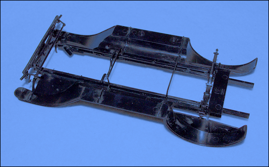
Flipping over the fender unit, I installed the rails in their correct position, then added the front axle and rear springs, along with the steering box, fender braces and frame braces. And yes, I know that the V-brace...actually more of a U shape...was installed upside down. It was corrected before the engine was added. Finally, I had a reasonably sturdy fender/frame unit that could be handled without it falling apart. I then sprayed the underside of the chassis with Model Master FS37038 Flat Black and the uppersurface of the fender unit with Boyd High Gloss Black and left it to dry.
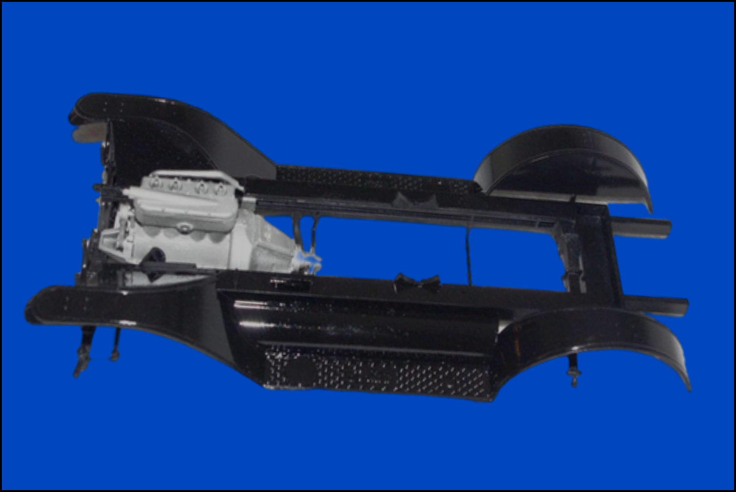
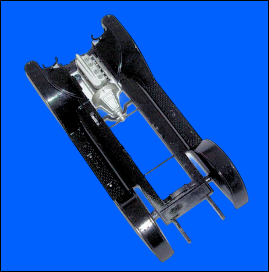
With the paint dry, it was time to add the engine. Be advised that this is where things get really touchy, if they havenít been already. The engine mounts fit into slots that are created when you install the assembled frame unit to the fenders (with the engine already mounted to the rails), but I had to take a different tack. Since the slots had already been created by the installation of the rails, I slipped one of the engine mount ears into its slot on one rail, then carefully and gently worked the engine down between the rail opening, applying just enough pressure to spread the opening for the opposite ear to slip into place. Be careful here because too much and youíll pop the joint where the front axle meets the frame, but you donít have too much to worry about because the joint is easily repaired if you screw up.
The two previous photos should provide enough viewing angles to keep you out of trouble. By the way, note that the V-brace mounts under the rear of the transmission.
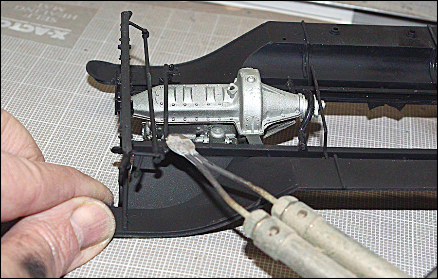
Since the kit advertises working steering, a steering link has to be installed. Running from the gearbox to the right-hand side of the axle, you have to flare a pin in order to trap the link and create a functional steering system. This method is as old as the hills and requires nothing more that a hot knife blade or the tip of a soldering iron. You can even get the job done with a small flathead nail driven into a wood dowel that is heated over a candle flame or the flame of a gas kitchen range or... Whatever method you use, just be careful not to flare the pin too far or youíll melt everything together.
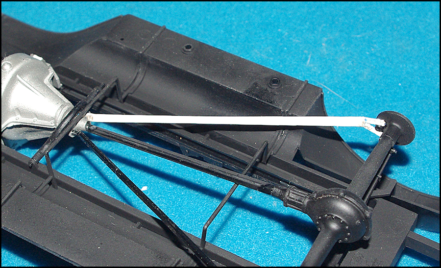
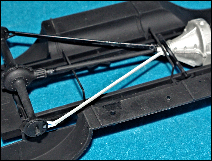
The last step in the fender/chassis assembly is to add the drive shaft, rear axle/differential and a pair of diagonal stays (braces) and that's where my next problem came from, courtesy of the kit's previous owner. One stay was missing and the other was broken. Since both parts were present, the broken one was fairly easily repaired, but the missing one was another story. My only choice was to use a piece of .o46" white styrene, cut to match the length of the repaired one.
A stud was carved on one end to fit a hole in the engine coupling, while the other end was split to form a Y that fit the wheel hub. Despite appearances to the contrary in this shot, give it a coat of Model Master FS37038 Flat Black and you'll never know it wasn't a kit part. |
|
| Return to home page | |
|
|
|
